
Zahner
—
Crimping
Intern - Summer 2019
Worked at Zahner developing a way to crimp wall studs into curves. The resulting stud would be used to hold panels that skin buildings. The crimping device was modeled off of the curveatrack crimping tool. Using an input surface in Rhino, a Grasshopper program split up the surface into a set of curves that would represent the bent studs. Using a standard angle that the crimper bends into the stud, the curve is unbent into a flat stud with points along the line that represent crimp locations.
The locations are collected into an excel file that a python program reads and sends into a Vention one axis robot. A 3D printed attachement connects the wall stud to the robot. The robot then moves the stud precisely according to the crimp locations and pauses to allow the stud to be crimped. The built crimper is attached to the end of the robot and crimps the stud at the crimping locations as the stud is moved by the robot.
Modeled in SolidWorks and Rhino using Grasshopper.


The first step in creating the bent studs was to construct a crimping device. The device’s design was inspired by
the curveatrack crimping tool. The design was modeled in SolidWorks including all of the McMaster parts ordered to construct the device. Manufacturing Orders were created for each part for the shop including Brake Tickets.

I proceeded with a mechanism that rotates the projector around a stationary vat in order to overcome the time increase from enlarging the current CAL design to print larger objects. Therefore, the vat of resin never moves, and the mechanism no longer needs to wait to start projecting for the resin to settle into rotating at a constant angular momentum.
To rotate the mechanism, A large belt pulley sprocket is attached to the circular track, and the sprocket is then circled by a belt. To ensure the belt would not slip off of the sprocket, the sprocket was made of two halves with an outer lip that bolted together. The belt is driven by a motor, and a tensioner is included to ensure the belt does not have any slack.
To rotate the mechanism, A large belt pulley sprocket is attached to the circular track, and the sprocket is then circled by a belt. To ensure the belt would not slip off of the sprocket, the sprocket was made of two halves with an outer lip that bolted together. The belt is driven by a motor, and a tensioner is included to ensure the belt does not have any slack.

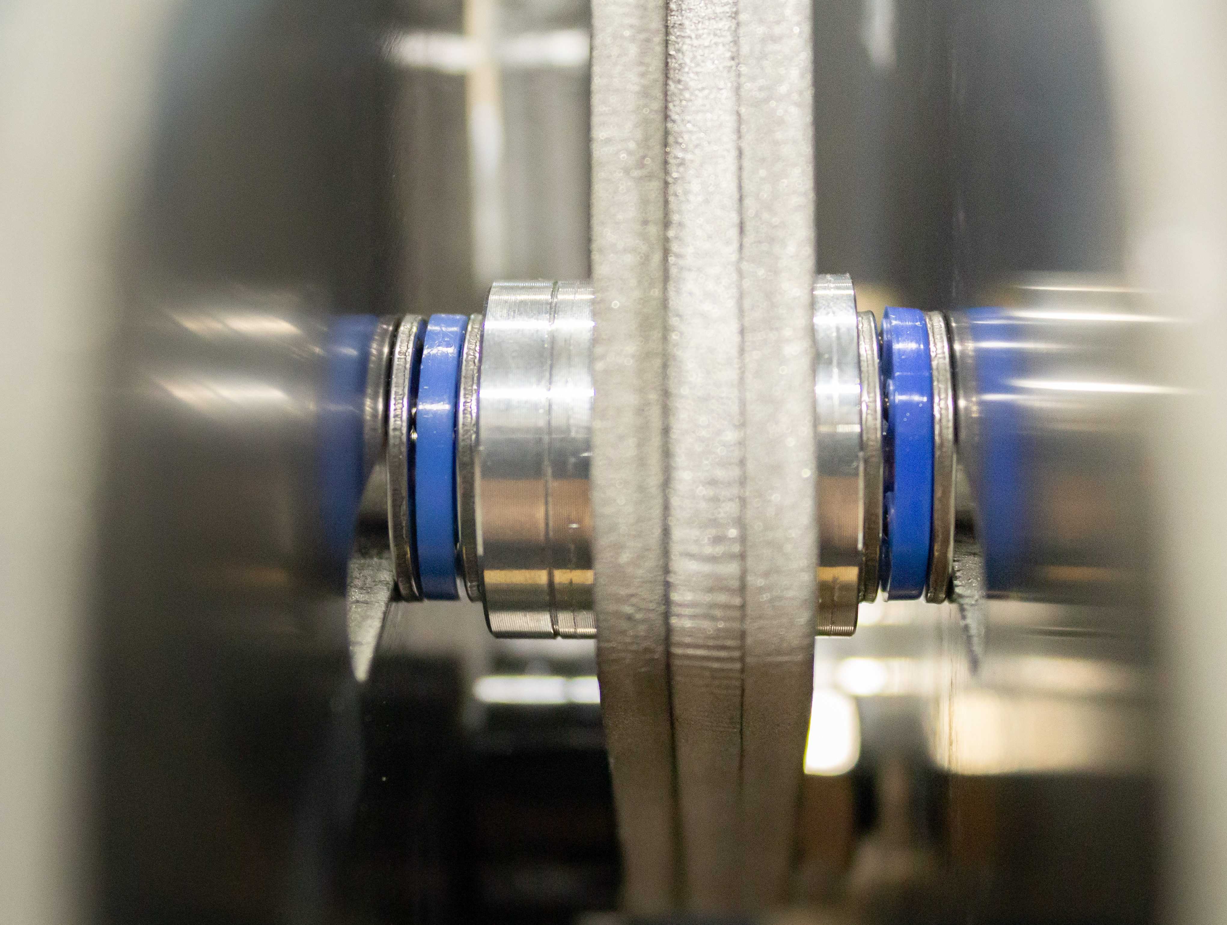
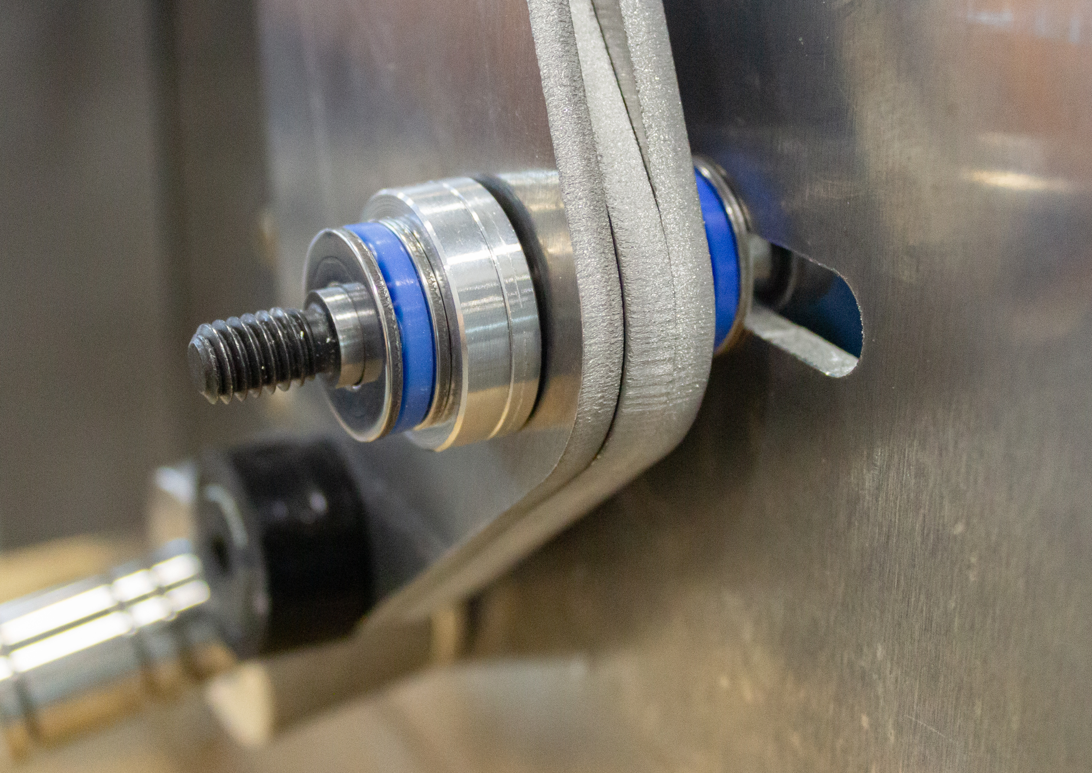


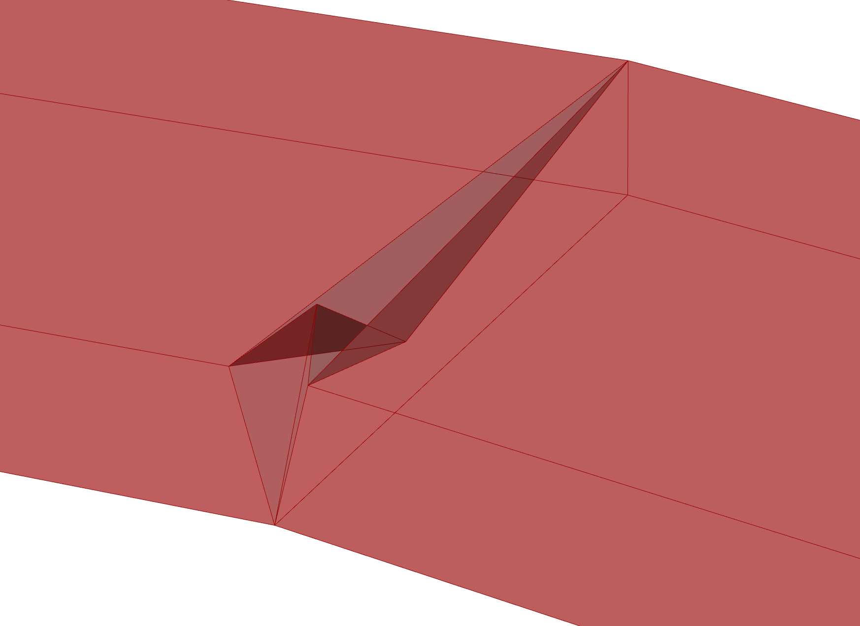
When the constructed crimper bent a stud, it created a crimp in the image to the left. This crimp was modeled in Rhino as shown on the right.
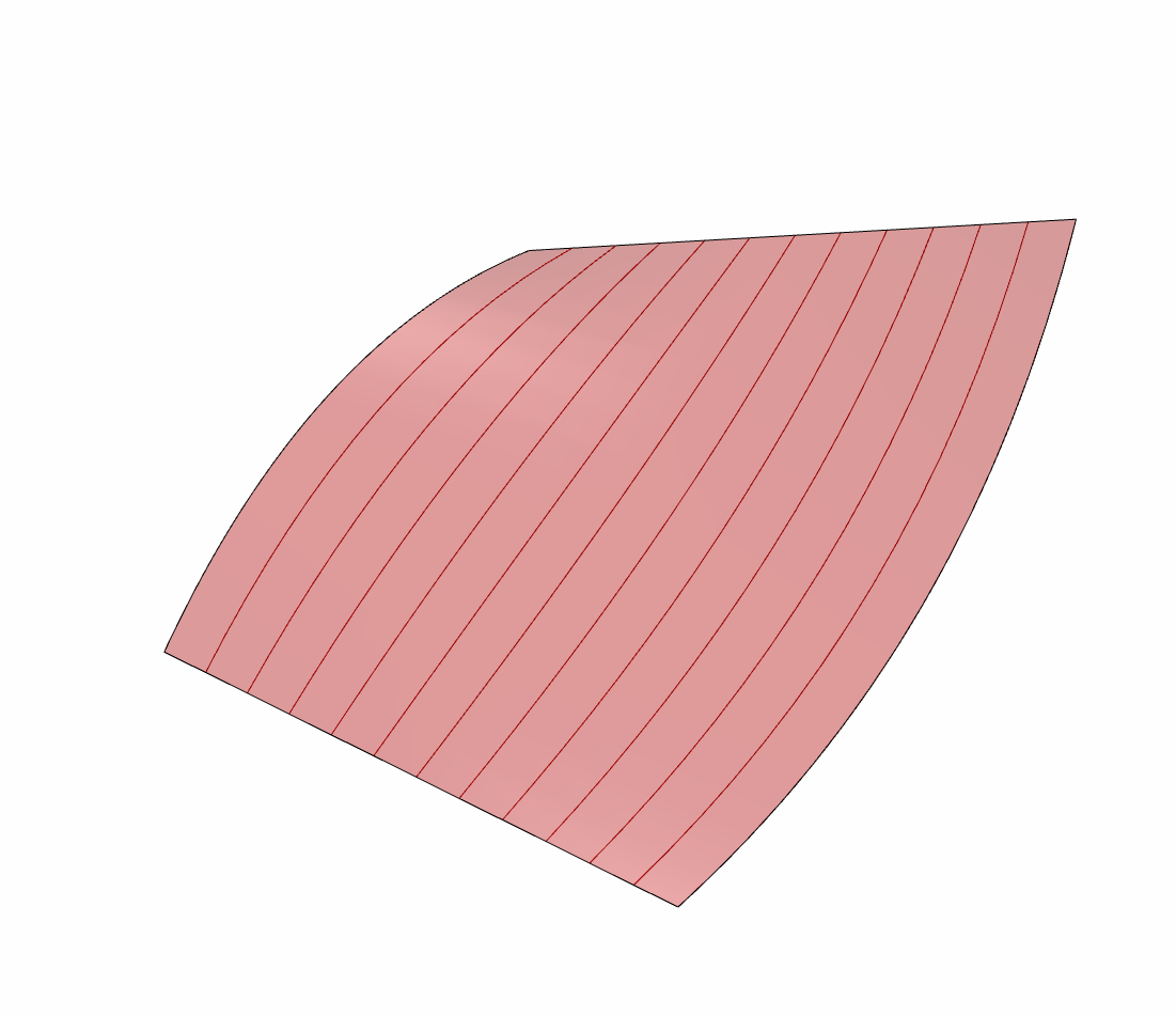

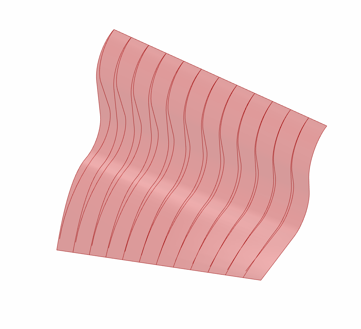
A grasshopper program accepted a surface that would be cut into sections as shown in the photo on the left. The curves represent the ideal shape of a stud to represent the curve. These curves are recreated by the program by bending straight lines at certain locations. These bent lines mimic the curvature of the original curve. The bent lines that represent a crimped stud are placed on the surface to compare the studs to the original curve in photo on the right.

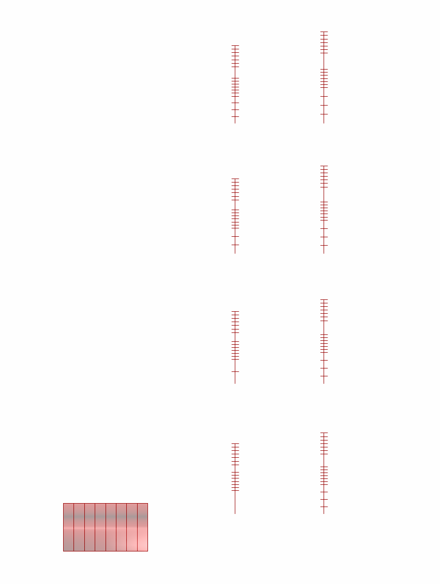
The image to the far left displays a surface with equally spaced curves that represent the desired stud shape. To the left displays the surface and curves from the far left in the lower left hand corner. The curves have been stretched into straight lines to represent the uncrimped studs. The program determines how many crimps and the distance between them to replicate the curves as best possible. On the right, the lines bent at the crimped locations were placed on the surface as abocvto compare the bent studs to the ideal curves.
A one axis robot from Vention was utilized to move a stud at precise distances. Therefore, the lengths between each crimp could be calculated and input in a python program written to control the robot with a keyboard.


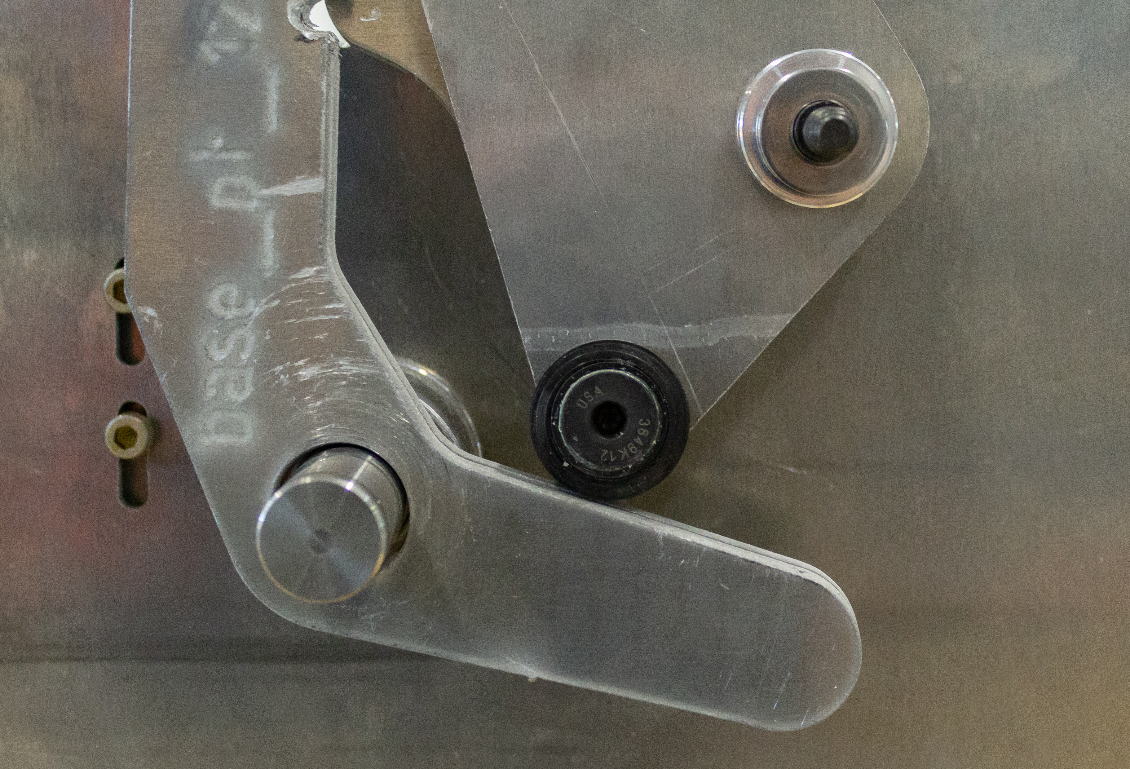
The crimper was attached to the end of the Vention machine using the geometry and materials associated with the machine.


A component was modeled in SolidWorks and 3D-printed to attach the stud to the movement plate on the vention machine. The component allowed for the stud to be easily fed through the back of the print while providing enough grip to move the stud when the plate moved. The connecting device gripped the stud by its side with a slot mechanism that could be slid to press into the side of the stud and secured by a screw. The top of the stud was held down by the top portion of this component that is slid into slots and held into place with a snap-fit


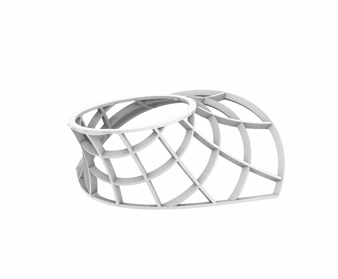

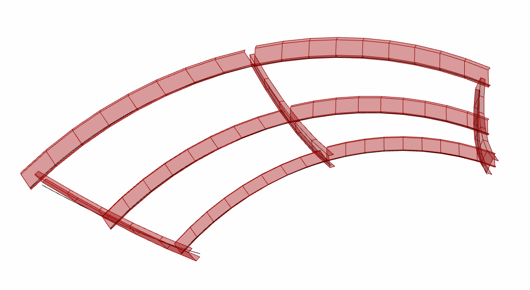
The final test case was to create a section of the structure to the left.A portion of the top of the structure was isolated and split into twelve curves as pictured below to the left.


The curves on the far left represent the studs that would be crimped and placed together to make the circled section of the structure.
The original curves are displayed in black. The green curves are of the reconstructed curves from studs that have been crimped. The image on the far right contains dots at the location of each crimp.


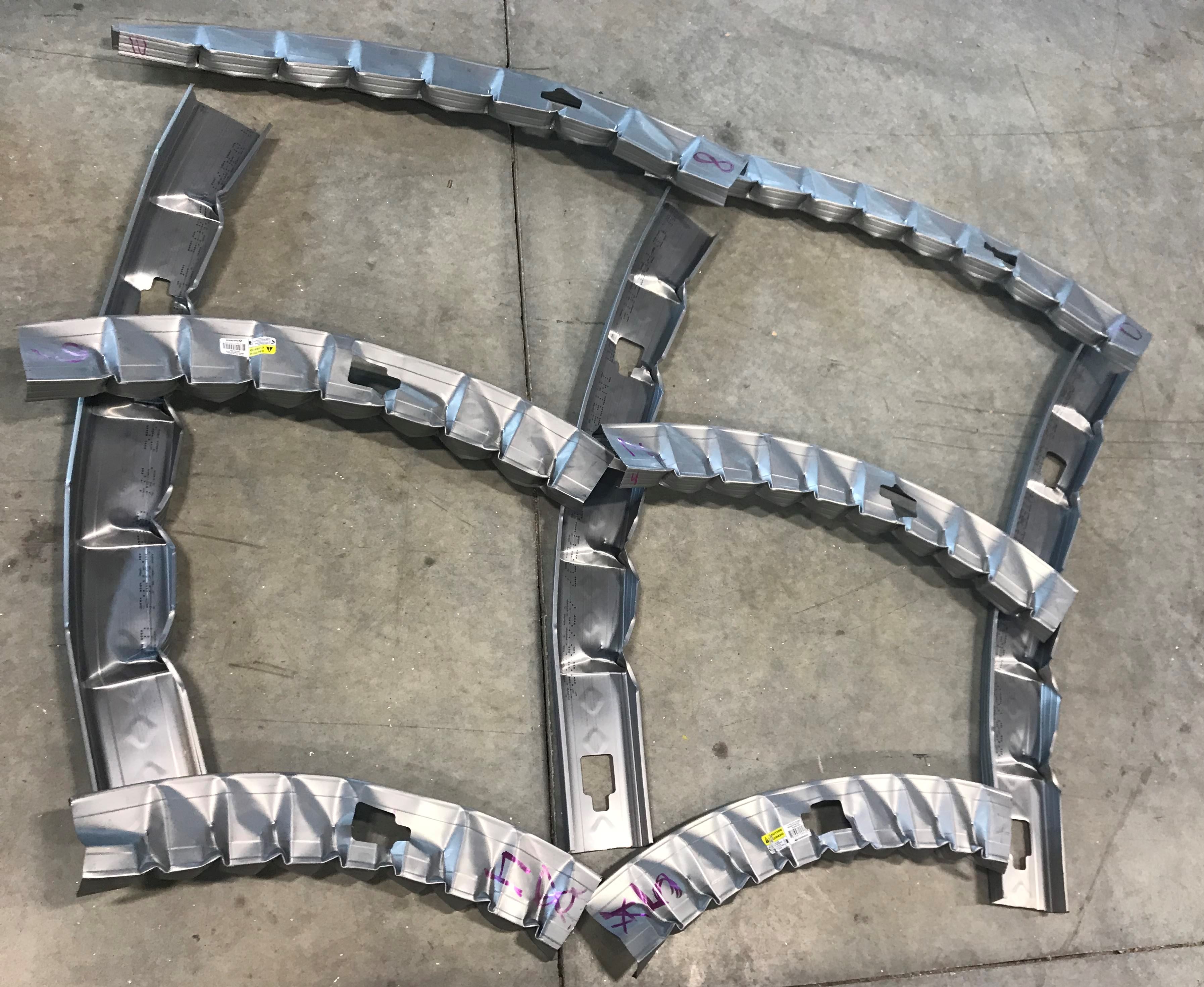
The studs were crimped at the length of the curves and labeled shown in the photo to the left. The photo to the left displays the crimped studs before assembly. The photos below compare the assembled structure to the desired structure. A video exemplifying the crimping process can be found here.


The measurements taken of the constructed figure revealed curvatures that were slightly smaller than those in the Rhino model. This can be explained by the callibration of the angle each crimp creates. With a more precise way to determine the angle of each crimp, the curvature of the studs will be more accurate to the desired curves. The smaller measurements are most likely due to an overestimation of the angle each crimp creates. Therefore, the program determined there should be more crimps for each stud to create the desired curvature than the stud would actually need.